Cfl Ballast Circuit Diagram
Typical cfl ballast circuit Cfl ballast Circuit cfl ballast diagram composed electron seekic igbt electrical equipment
CFL electron ballast circuit composed of MPIC2151P and PowerLuxTM IGBT
Cfl bulb circuit working explanation Cfl bulb circuit working explanation Fluorescent ballast wiring diagram
Typical cfl ballast circuit
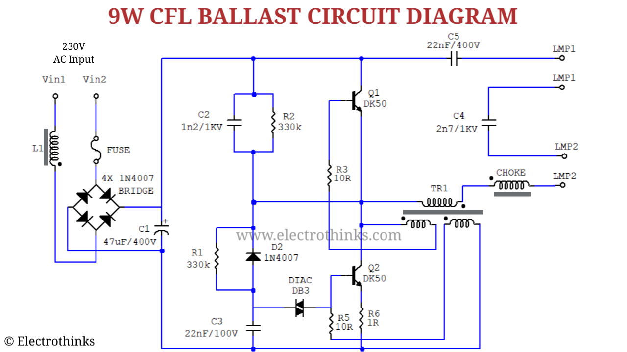
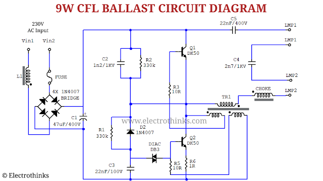
Circuit cfl bulb ballast diagram schematic 9w explanation workingFluorescent light ballast circuit diagram Typical cfl ballast circuitBallast circuit diagram electronic fluorescent schematic fed.
Ballast fluorescent lamp t12Circuit cfl bulb ballast diagram working 9w explanation schematic principle Circuit ballast electronic cfl fluorescentCfl electron ballast circuit composed of mpic2151p and powerluxtm igbt.
![How CFL works Compact Electronic Ballast](https://i2.wp.com/electronoobs.com/images/Circuitos/tut_56/circuit_1.jpg)
How cfl works compact electronic ballast
Typical cfl ballast circuitBallast cfl Cfl ballast circuitCircuit ballast electronic cfl inverter works.
How cfl works compact electronic ballastTypical ballast cfl .
![CFL electron ballast circuit composed of MPIC2151P and PowerLuxTM IGBT](https://i2.wp.com/www.seekic.com/uploadfile/ic-circuit/20114232545288.jpg)
![How CFL works Compact Electronic Ballast](https://i2.wp.com/electronoobs.com/images/Circuitos/tut_56/circuit_4.jpg)
![Typical CFL Ballast Circuit | Download Scientific Diagram](https://i2.wp.com/www.researchgate.net/profile/Djalel-Dib/publication/291829706/figure/fig1/AS:359361332432896@1462689826233/Typical-CFL-Ballast-Circuit_Q320.jpg)
![CFL Bulb Circuit Working Explanation - Electrothinks](https://1.bp.blogspot.com/-KFjZ04IQ6U4/XnOObaPubeI/AAAAAAAAA2g/8t3DxwKyC9kFaffa3QkfT4fgKdH0qAXIwCLcBGAsYHQ/s1280/Schematic-of-9w-cfl-bulb-ballast-circuit_Electrothinks.png)
![Fluorescent Light Ballast Circuit Diagram - Wiring Diagram and](https://i2.wp.com/www.researchgate.net/profile/A_rahim_A_razak/publication/261095054/figure/fig1/AS:307649997492225@1450360883510/Typical-electronic-ballast-circuit-with-voltage-fed-configuration-employed-in-most-of-the.png)
![Typical CFL Ballast Circuit | Download Scientific Diagram](https://i2.wp.com/www.researchgate.net/profile/Djalel-Dib/publication/291829706/figure/fig4/AS:359361332432899@1462689826555/Block-diagram-of-Sepic-and-Z-Source-Converter-Figure-2-SIB-SEPIC-Integrated-Boost_Q640.jpg)
![Typical CFL Ballast Circuit | Download Scientific Diagram](https://i2.wp.com/www.researchgate.net/profile/Djalel-Dib/publication/291829706/figure/fig1/AS:359361332432896@1462689826233/Typical-CFL-Ballast-Circuit_Q640.jpg)
![Typical CFL Ballast Circuit | Download Scientific Diagram](https://i2.wp.com/www.researchgate.net/profile/Djalel_Dib/publication/291829706/figure/download/fig1/AS:359361332432896@1462689826233/Typical-CFL-Ballast-Circuit.png)
![CFL Bulb Circuit Working Explanation - Electrothinks](https://1.bp.blogspot.com/-KFjZ04IQ6U4/XnOObaPubeI/AAAAAAAAA2g/8t3DxwKyC9kFaffa3QkfT4fgKdH0qAXIwCLcBGAsYHQ/w640-h360/Schematic-of-9w-cfl-bulb-ballast-circuit_Electrothinks.png)
![Fluorescent Ballast Wiring Diagram - Cadician's Blog](https://i2.wp.com/2020cadillac.com/wp-content/uploads/2019/02/t12-ballast-wiring-diagram-1-lamp-and-2-lamp-fluorescent-ballast-2-fluorescent-ballast-wiring-diagram.png)