Circuit Diagram Of Nor Gate
Xor nand logic nor gates xnor circuit vhdl simulate verify truth input circuits tutorial engineersgarage inverter scosche inputs ckt combined Circuit transistor nor gate two seekic ends input basic diagram The transistor nor gate circuit with two input ends
VHDL Tutorial – 5: Design, simulate and verify NAND, NOR, XOR and XNOR
Gate nor pmos schematic logic digital using ic series its two universal given below Nor gate circuit diagram & working explanation Study engineering: nor gate
Vhdl tutorial – 5: design, simulate and verify nand, nor, xor and xnor
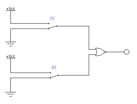
Nor gate logic gates truth table output introduction its high technology inputs ifCmos nor gate Nor gate using ex diagram implementation circuit ic precautions block makeNor gates xor vhdl output.
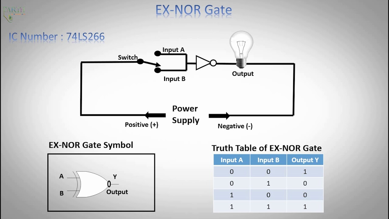
Nor gate circuit rise fall question time transistor symbol standard figure attachments img101 gifNor gate: what is it? (working principle & circuit diagram) Nor gateNor gate ex logic exclusive table truth.
Introduction to logic gates
Logic ex nor gate tutorial with logic exclusive nor gate truth tableCircuit nor gate diagram working explanation circuits resistors electronic necessary chosen integrated pull down these Conversion of nor gate to basic gatesDigital logic nor gate(universal gate).
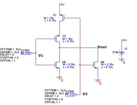
Vhdl tutorial – 8: nor gate as a universal gateNor electrical4u principle Nor gate cmos circuit diagram logic pmos touch keep transistorsGate nor circuit diagram.


